One thing is sure. We have to do something. We have to do the best we know how at the moment… If it doesn’t turn out right, we can modify it as we go along.
Modifiers are routines that take objects and move them or change them somehow. Like CircularArray() copies and moves objects into circular arrays, or Position() aligns an object with a given vector, or SectorCut() cuts a 'sector' from an object.
The Routines.
CircularArray()
CircularArray(Radius=30,AngleBetween=30,Number=4,Start=0,Static=false)
-
Radius, scalar, radius of the array.
-
AngleBetween, scalar, angle between the individual elements.
-
Number, integer, number of elements in the array.
-
Start, scalar, start-angle, CCW ↺ from the positive X-axis.
-
Static, Boolean, elements keep their original orientation if true.
Generate a circular array of the original element.
In the image, the Static parameter has been set to true for the MapleLeaf SVG_Shape()s, so they keep their original orientation in the array.
The ArrowHead()s have the Static parameter set to false, causing them to turn with the rotation.
include<TheGHOUL/Config.scad>
$AnimSegs=4;
$vpt=[0,0,0];$vpr=[45,0,30];$vpd=80;

color(RED)
linear_extrude(2,scale=0)
Star(12,5,Schlaefli=4,Centered=true);

Animate([0,0,1,4])
color(DSG){ No=floor(8*$AnFrac); // Integer stepped value
    CircularArray(Radius=8,IncludedAngle=360/8*(No-1),Number=No,Start=0,Static=false)
    linear_extrude(1,scale=0)
    ArrowHead(3,3,1); }

Animate([1.1,1.1,2,4])
color(SVR){ No=floor(8*$AnFrac);
    CircularArray(Radius=9,IncludedAngle=360/8*(No-1),Number=No,Start=22.5,Static=false)
    linear_extrude(0.5,scale=0)
    ArrowHead(1.5,1.5,0.5); }

Animate([2.1,2.1,3,4])
color(RED){ No=floor(16*$AnFrac);
    CircularArray(Radius=15,IncludedAngle=360/16*(No-1),Number=No,Static=true)
    linear_extrude(0.5,scale=0.8)
    SVG_Shape(DemoShapes,"MapleLeaf",Size=[5/4000,5/4000],Center=true,Home=false); }

translate([-25,0,0])
CoordinateSystem(Size=4,Thickness=0.4,Points=[0,0.3,1],Polar=false);|
|
In the code above, by giving color() a scope (the curly brackets), the special variable $AnFrac, provided by Animate() becomes available within the entire scope. It’s a neat trick…
|
LinearArray()
LinearArray(Spacing=[0,0,0],Number=[1,1,1],Center=false)
-
Spacing, a vector of length 1, 2, or 3 or a scalar, in which case it is expanded into a symmetrical 3-vector.
-
Number, a vector of length 1, 2, or 3 or an integer, in which case it is expanded into a 3-vector with .y=.z=1.
There’s not much to be said about this one; it generates a linear, rectangular or 3D array of children().
LinearArray(Spacing=[10,6,1],Number=[3,5,2])  // a cuboid array.
LinearArray(Spacing=10,Number=[3,5])          // a rectangular array.
LinearArray(Spacing=[10,20],Number=[3,5])     // a rectangular array.
LinearArray(Spacing=10,Number=7)              // a linear array.
OutRadius()
OutRadius(Radius,TG=true)
-
Radius, scalar, radius of the inscribed circle.
-
TG, Boolean, flag switch between OpenSCAD or The GHOUL’s method for determining circle fragment numbers, to use OpenSCAD terminology. It defaults to the more sensible method (I would think so) used by The GHOUL.
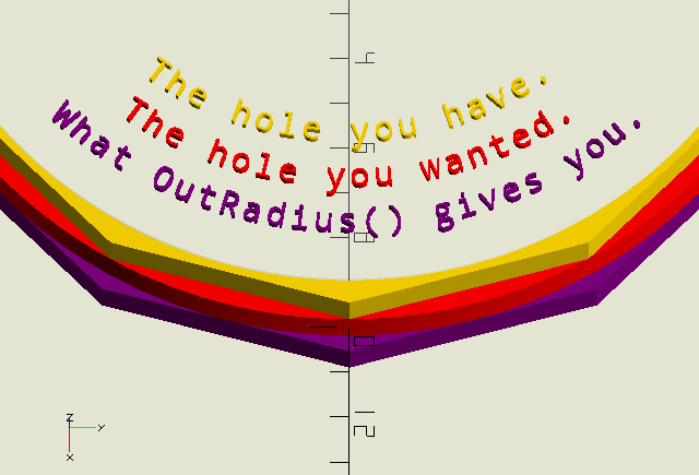
Digital expressions of the real world can only be approximations. Circles, and thus holes, in OpenSCAD are not round but actually polygons that are inscribed in the specified radius. If you’re wondering why your 10 mm shaft doesn’t fit your 10 mm hole, that’ll be why. OutRadius() generates a correction factor to compensate for this, resulting in a circumscribed polygon, i.e., a polygon with sides forming tangents to the desired circle. To get the desired result, i.e., a hole that’s big enough to accommodate a bolt or shaft of the required dimension, make your call like this (the $fn declaration is optional of course):
circle(OutRadius(r),$fn=…)
Because OutRadius() is called from within the circle() call, it shares $fn from that namespace, whether $fn is specified in the call, or from the top level.
|
|
The GHOUL and OpenSCAD use slightly different methods to determine how many 'fragments' or corners a circle should have. See the sidebar here for more information. |
Position()
Position(Vector,Base=[0,0,0],Roll=0,Alignment="Z",Center=[0,0,0])
-
Vector, a direction vector to align
children()with. -
Base, a 3D vertex where
children()will be translated to. -
Roll, angle, rotation angle around Vector applied in place to
children(). -
Alignment, string; for objects that are not aligned with the positive Z-axis, the results of
Position()are not intuitive. To improve on this, the initial alignment axis of the object can be specified in order to get results that 'feel right'. The image shows the result of an 'X-aligned' object (yes, that’s theToonPlane()module at work there) with and withoutAlignment="X".-
"X", for objects aligned with the positive X-axis that have their 'top' facing up, this works well for shapes with a directional character that are positioned pointing East as per the GHOUL conventions.
-
"Y", for objects aligned with the positive Y-axis that have their 'top' facing up, this works well for text.
-
-
Center, a 3D vertex around which the rotation of
children()takes place. Default=[0,0,0].
Position the children() objects with a direction defined by Vector.
Position() uses
VectorToIncAz(), which means the rotation is accomplished by an initial rotation around the Y-axis, followed by a rotation around the Z-axis. This works well for objects that have more of an 'end' such as arrows or cylinders, aligned with the positive Z-axis, but may give unexpected results with objects that have more of a 'top' such as text or a linear_extrude()ed shape. For the latter type of object, Position() allows you to specify the alignment axis to get more intuitive results, depending on your perspective.
PosX2D()
PosX2D(Size)
-
Size, scalar, size in units of the
square()used in thedifference()operation. Must be bigger than the shape being trimmed…
PosX2D uses a difference() operation to trim the negatve-X part away from a 2D shape or polygon. Used by e.g. Cap().
PosX3D()
PosX3D(Size)
-
Size, scalar, size in units of the
cube()used in thedifference()operation. Must be bigger than the object being trimmed…
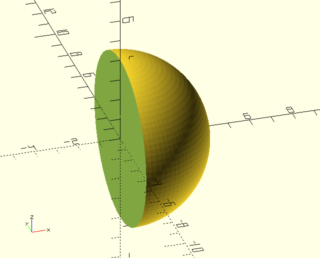
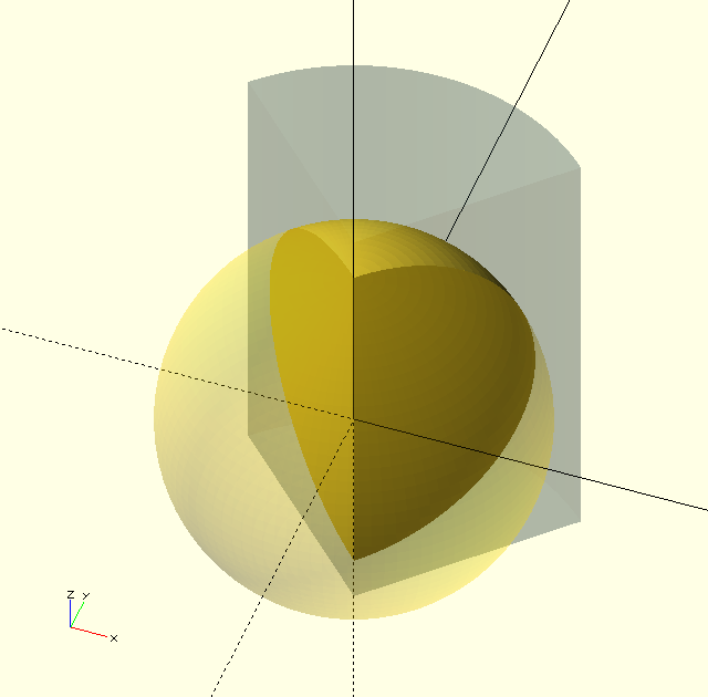
PosX3D() uses a difference() operation to trim the negatve-X part away from a 3D object. Use it to get half a sphere for example.
PosX3D(10);
sphere(r=4);
PosZ3D()
PosZ3D(Size)
-
Size, scalar, size in units of the
cube()used in thedifference()operation. Must be bigger than the object being trimmed…
Just like PosX3D(), but trims the negatve-Z part away from a 3D object.
ScreenCoords()
ScreenCoords(Vertex)
-
Vertex, 3D vertex.
Converts World CS vertices or vectors into Screen CS vertices and vectors. My laptop screen is about 35 'ScreenPosition' units wide and 18 high. The origin lies on $vpt, i.e., it is always screen-center.
ScreenMove()
ScreenMove(Vector)
-
Vector, translation vector [x,y,z].
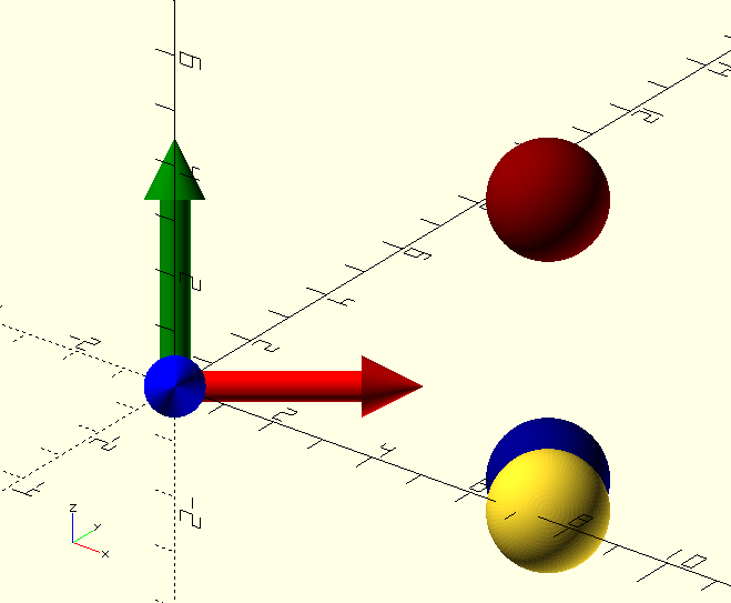
ScreenMove() moves its children() relative to the screen-UCS (see image) whith positive-X along the bottom of the screen, positive-Y along the left edge, and positive-Z coming 'out of' the screen. The Z-value has no effect on the size of objects, because OpenSCAD is no PoVRay; it’s clear though that the yellow sphere has moved 'up' from the screen, as it is intersected by the WCS X-axis which is coming 'towards' us in the image, and the more obvious fact that the blue sphere is behind it… ScreenMove()'s cousin ScreenPosition() has compensation parameters to (somewhat) take care of that.
ScreenUCS(Size=4);

ScreenMove([6,-2,3])
sphere(r=1);

color(DBL)
ScreenMove([6,-1.5,0])
sphere(r=1);

color(DRD)
ScreenMove([6,3,50])
sphere(r=1);
ScreenPosition()
ScreenPosition(Location=[0,-5,0],SizeCompensation=40,ScreenFactor=40)
-
Location, 3D point, location of the object on the screen.
-
SizeCompensation, scalar, compensates for zoom, i.e., changes in $vpd.
-
ScreenFactor, scalar, compensates for translation due to zoom, i.e., changes in $vpd.
ScreenPosition() will maintain it’s children()'s on screen position after a regen, regardless of zoom, translation or rotation.
My laptop screen is about 35 'ScreenPosition' units wide and 18 high. The origin lies on $vpt, i.e., it is always screen-center. It’s useful for putting a background behind a
ScreenText(), during ViewPort() animations, but probably not much else.
ScreenUCS()
ScreenUCS(Size=1)
-
Size, scalar, size of the UCS or vector-length.
The function returns the unit-base-vectors of a coordinate system (CS) that has a Z=0 plane that is parallel to the screen (the 'Screen' CS). The module displays the Screen CS as three coloured arrows.
SectorCut()
SectorCut(StartAngle,Angle,Radius,Height,Centered=true,Move=[0,0,0],Color=BLK,Convexity=10)
-
StartAngle, scalar, start-angle of the sector.
-
Angle, scalar, (total) angle of the sector.
-
Radius, scalar, radius of the sector.
-
Height, scalar, height of the sector.
-
Centered, Boolean, centered vertically around the origin if true.
-
Move, vector, translation vector of the sector.
-
Color, The GHOUL colour, colours the cutting surfaces.
-
Convexity, integer, OpenSCAD convexity parameter, see the OpenSCAD manual entry.
SectorCut() cuts a sector out of it’s children(). Make sure to set the Convexity value high enough; 10 is a good point to start when shapes get more complex, or when several difference() operations have been performed on an object. If weird shadow effects appear: increase the Convexity value.
SectorSlice()
SectorSlice(StartAngle,Angle,Radius,Height,Centered=true,Move=[0,0,0],Color=BLK,Convexity=10)
-
StartAngle, scalar, start-angle of the sector.
-
Angle, scalar, (total) angle of the sector.
-
Radius, scalar, radius of the sector.
-
Height, scalar, height of the sector.
-
Centered, Boolean, centered vertically around the origin if true.
-
Move, vector, translation vector of the sector.
-
Color, The GHOUL colour, colours the cutting surfaces.
-
Convexity, integer, OpenSCAD convexity parameter, see the OpenSCAD manual entry.
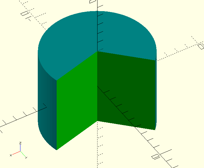
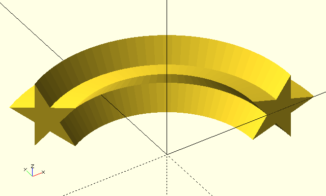
Where SectorCut() removes a sector, SectorSlice() keeps a sector out of it’s children(), the same caution about Convexity holds true here.
Torus()
Torus(Radius,Angle)
-
Radius, radius of the torus.
-
Angle, included angle of the torus-sector.
As of yet, it’s just a name place-holder and an alias for rotate_extrude(), but I have plans; Great Plans…
Tumble()
Tumble(TumbleTuple=[0,0,0],Factor=$t)
-
TumbleTuple, a tuple of three scalars, each being a multiplier for rotation around the X, Y, and Z axis respectively, determining the number of full revolutions
children()will make in the time-span of the animation.
The prettiest results are achieved when at least one multiplier is even and another odd. Watch out for non-integer values, they can cause ugly discontinuities. -
Factor, fraction, animation factor; generally this will be $t.
Tumble() is humble, but it does such pretty things! I’m mesmerised by the results every time, it’s addictive! Tumble() makes it’s children() tumble; obviously you need to be in the animation view in OpenSCAD .
It’s pretty much useless for anything but making GIFs like the one here, but the result is Purrdeee!
//    Tumble([2,1,1.5],$t)
module Tumble(TumbleTuple=[0,0,0],Factor){
    rotate([
         Factor*360*TumbleTuple.x
        ,Factor*360*TumbleTuple.y
        ,Factor*360*TumbleTuple.z
    ])
    children();
}