Alice: How long is forever? White Rabbit: Sometimes, just one second.
A dog’s breakfast.
Gears, in clocks, have some funky (non-universal) naming conventions; The GHOUL uses the convention that the larger gear is called the 'wheel', and it has teeth. The smaller gear is always called the 'pinion', and it doesn’t have teeth, but has leaves instead. In the 'going trains' of clocks and watches, the gears tend to have high ratios, meaning that the wheels are large, driving small pinions. In fact, the pinions in clocks and watches often only have six leaves, sometimes even fewer.
Clock gears are also—almost always—cycloid gears; a horror show, a dog’s breakfast, compared to 'proper' involute gears. They are so, because unlike involute gears, clock gears, running by necessity without lubrication are, in an effort to prevent friction, designed to avoid contact between the teeth and leaves before the 'line of centres' as much as possible, if not completely.[1] Where in involute gears this contact is very important to achieve smooth running gears with a high contact ratio, the friction that is created in that portion of the 'line of action' could stop a clock. Luckily, we’re dealing with—for all intents and purposes—invariable, continuous loads, and very low powers (see sidebar below), so we can afford lots of backlash, or 'shake' in clockmaker’s language, and minimal contact. In the GIF here, the contact point can be seen as a blue or red sphere. Initially, before the line of centres, the contact point, shown in blue, follows the wheel’s pitch circle; this is where friction is most detrimental. Although theoretically there is no contact here, the slightest wear or manufacturing imprecision will allow there to be some. Past the line of centres, the contact point, shown in red, travels along a circular path with a radius equal to that of the 'generating circle'—about which more in a moment. The blue, green, and red circles in the GIF are the wheel and pinion pitch circles, and the generating circle.
In a nutshell, these horrible cycloid gears are sloppy, they have appalling contact ratios, and they wouldn’t live a day in a variable power application, but they offer ultra low friction, and very large wheels can mesh effectively with pinions with extremely low leaf numbers, so ridiculously large ratios can be achieved with just a handful of gears—things an involute gear can only dream of.[2] As a final bonus—although irrelevant in a 3D printing context—they’re very easy to manufacture with relatively simple machinery—in fact, in the early days of clock-making, they were made exclusively with hand tools, and nothing stops you doing so now.
Since we’re only interested in the driving (i.e. retreating) side of the line of action (after the line of centres) where there is only ever contact between the addendum of the teeth and the dedendum of the leaves, both are cycloids, or 'common trochoids'. As a generating circle we use half the pinion’s pitch circle diameter so the leaf dedendums will be straight radial flanks, as demonstrated handsomely in the image here by the 'bonus' module ShowTrochoid(4,-2,2); from TheGHOUL/Lib/Curves/Roulettes.scad. For the wheel we use the same size generating circle as the leaf—a requirement for them to mesh properly. The wheel’s roots, as well as the pinion’s leaves' roots and tips are all simple circular curves.
ClockWheel()
ClockWheel(Wheel, Pinion, DP=1, Shake=0.025, Tip=0.1, RootClearance=0, ID=0, String="Gear", Thickness=1, Mesh=0)
-
Wheel, Integer, number of teeth on the wheel.
-
Pinion, Integer, number of leaves on the pinion. This is required here, because the wheel’s teeth are based on a generating circle, which is itself based on the pinion’s pitch circle diameter.
-
DP, Real, or more likely a Rational, diametral pitch. This is the number of teeth per unit diameter of the pitch circle.
-
Shake, Fraction of the tooth-width, the clockmaker’s word for 'play' or 'slack'.
-
Tip, Dimension, flat or cropped tooth-tip width.
-
RootClearance, Dimension, removes material at the roots to provide clearance with the tips of teeth and leaves, 0 is usually fine for both, if some Shake is given to the wheel.
-
ID, Dimension, internal diameter, shaft hole, bore.
-
String, Reference for console output.
-
Thickness, Dimension, thickness of the gear, i.e., axial dimension.
-
Mesh, Rational, most likely 1/2, rotates gear by Mesh number of pitches to maintain mesh in the viewer—usually required for a gear with an uneven number of teeth.
Traditionally, clock gear tooth sizes have been specified in Diametral Pitch, i.e., the number of teeth per unit of the pitch circle diameter. For example, if DP=2 and the gear has 40 teeth, the pitch circle has a diameter of 40/2=20 units. A larger DP gives smaller teeth:
\[ DP [Teeth/Length] = \frac {Z [Teeth]}{PCD [Length]} \] |
(1a) |
The GHOUL’s routine adheres to this tradition, but if you’re more comfortable with the concept of Module than Diametral Pitch when thinking about gear teeth, since:
\[ M [Length/Tooth] = \frac {PCD [Length]}{Z [Teeth]} \] |
(1b) |
Then:
\[ DP [Teeth/Length] = \frac {[1]}{M [Length/Tooth]} \] |
(2) |
Which means you can just specify 1/M instead of DP and get the expected result. After all that painful malarkey, you may wonder why I didn’t just write an alias. Well, I did, but I wanted you to know the whys and whatfors.
ClockWheel_M(Wheel, Pinion, M, …) does exactly the same as it’s older brother, but takes Module input.
 Shake removes material at the flanks, roots and tips.
Some shake is required in clock gears to prevent binding, which would stop the clock.
Generally, it is sufficient to give some, say 0.05 shake to the wheel only; the wheel is bigger and stronger, and teeth—due to their shape—are inherently stronger than leaves; see the image to the right.
Shake removes material at the flanks, roots and tips.
Some shake is required in clock gears to prevent binding, which would stop the clock.
Generally, it is sufficient to give some, say 0.05 shake to the wheel only; the wheel is bigger and stronger, and teeth—due to their shape—are inherently stronger than leaves; see the image to the right.
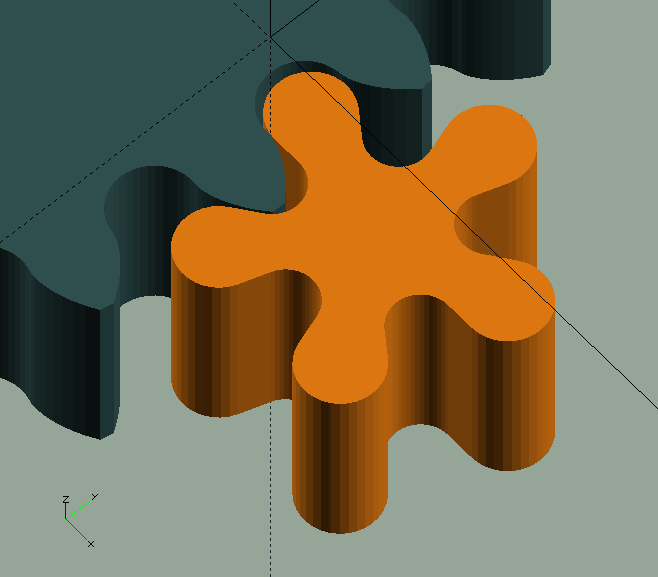
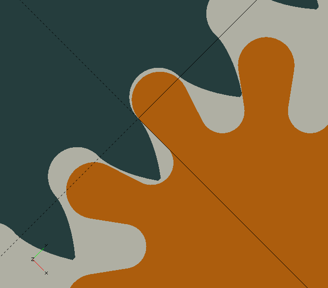
 When the pinion is very small, say with only 6 leaves, the roots of the leaves become weak. In a similar way to profile shift in involute gears, we can redistribute the (circular) pitch between the teeth and the leaves to strengthen the roots of the leaves.
By giving the wheel and pinion an equal but opposite amount of Shake, positive for the wheel but negative for the pinion, the total amount of shake remains the same, i.e., the 'play' or 'backlash' doesn’t change, but material is taken from the teeth and added to the leaves, giving them stronger roots.
A small value, like 0.05, has a significant effect.
The example (in the image to the left) is exaggerated.
When the pinion is very small, say with only 6 leaves, the roots of the leaves become weak. In a similar way to profile shift in involute gears, we can redistribute the (circular) pitch between the teeth and the leaves to strengthen the roots of the leaves.
By giving the wheel and pinion an equal but opposite amount of Shake, positive for the wheel but negative for the pinion, the total amount of shake remains the same, i.e., the 'play' or 'backlash' doesn’t change, but material is taken from the teeth and added to the leaves, giving them stronger roots.
A small value, like 0.05, has a significant effect.
The example (in the image to the left) is exaggerated.
ClockPinion()
ClockPinion() takes the same parameters as ClockWheel(), but, obviously, generates the pinion, and—just like with the wheel—there’s ClockPinion_M() which takes Module input instead of Diametral Pitch.
|
|
That there, what I just said about the same parameters, is a lie. ClockPinion() does take one additional (optional) parameter, WShake, i.e. the shake applied to it’s corresponding wheel. The root radius, and depth, of a pinion’s leaves depend on how deep the wheel’s teeth penetrate, and this in turn depends on the amount of shake applied to the wheel. If WShake is not specified, the root of the leaves will be based on a 'full-height' tooth, and be somewhat deeper—and thus weaker—than necessary, i.e., if it were based on the actual, shake dependent tooth height.
|
The functions
ClockWheel() and ClockPinion().
The routines we’ve just discussed are module()s that will generate a wheel or pinion object. In The GHOUL’s fashion, they do so using two 'helper' function()s with the same names, that take the same parameters but for the last two, Thickness, and Mesh, which only relate to objects; if you do specify those—because you were lazy and just copied the module call—they just get ignored. Although not considered user functions, they may come in handy if you want to post-process the data; like The GHOUL’s
Shapes,
they return a [[vertices],[paths]] tuple, ready for use by polygon(). Since all their parameters have just been treated, I’m not going to duplicate that here.
CamWheel()
CamWheel(OD=10, Cams=1, Step=3, ID=1, Rake=0, Thickness=1)
-
OD, Dimension, maximum OD of the camwheel.
-
Cams, Integer, number of cams.
-
Step, Dimension, height of the cam, or 'drop'.
-
ID, Dimension, internal diameter of the wheel.
-
Rake, Degrees, forward or reverse 'lean' of the step 'flank'.
Camwheels are used in clocks to activate or deactivate features, trigger alarms &c.
There is both a CamWheel() function and a module; the function ignores the Thickness parameter if you happen to specify it.
ChainWheel()
ChainWheel(Length=8, Width=4, Gauge=1, Links=20, Flange=2, ID=6, Shake=0, Resolution=0.4)
-
Length, Dimension, the maximum length dimension of one chain link.
-
width, Dimension, the maximum width dimension of one chain link.
-
Gauge, Dimension, sometimes called 'size', the diameter of the wire the chain links are made of.
-
Links, Integer, must be even, number of links to fit the circumference of the wheel.
-
Flange, Dimension, thickness of the flange, i.e., the width of the wheel’s 'rim' outside of the link-beds.
-
ID, Dimension, internal diameter of the wheel.
-
Shake, Dimension, backlash, play, excess room for the links in their 'bed'.
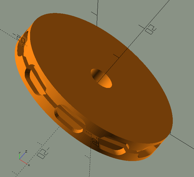
Chain wheels are used in clocks to drive the first wheel, also referred to as the 'barrel', with weights, suspended from a chain which fits in the recesses around the rim of the chain-wheel, and thus can not slip.
Due to the 3D character of chain wheels, there is no ChainWheel() function.
EOTWheel()
EOTWheel(RMin=20, RMax=50, ID=8, Ind=0.1, T=4)
-
RMin, Radial dimension, at minimum EOT value.
-
RMax, Radial dimension, at maximum EOT value.
-
ID, Internal diameter.
-
Ind, Dimension of the small diamond indicating Jan. 1st.
-
T, Thickness.
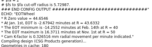
The 'Equation Of Time' (EOT) is the relationship between 'standard' time , and the time your sundial might indicate, if you had one. They differ, because earth is tilted, and travels an elliptical orbit. The EOT yields the number of minutes a sundial appears to be fast or slow, compared to standard time. Its minimum is approx. 14'6" slow around Feb. 11th, and its maximum is approx. 16'33" fast around Nov. 3rd. Near Apr. 15th, Jun. 13th, Sep. 1st, and Dec. 25th, the EOT value becomes 0, i.e., four times a year, your watch and the sun agree.
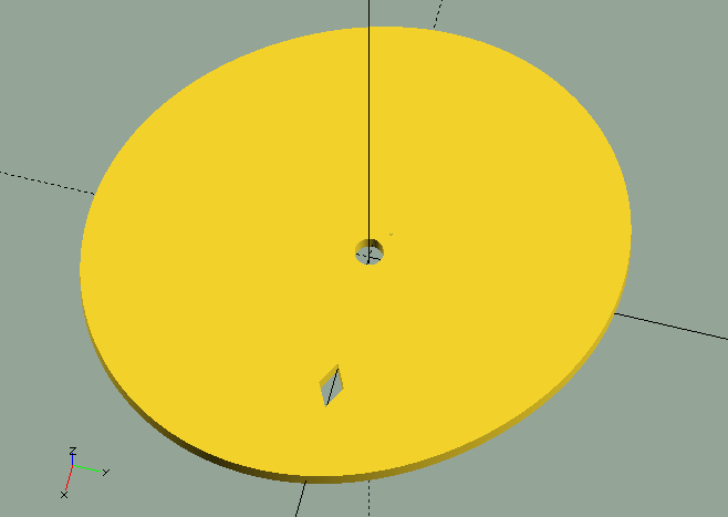
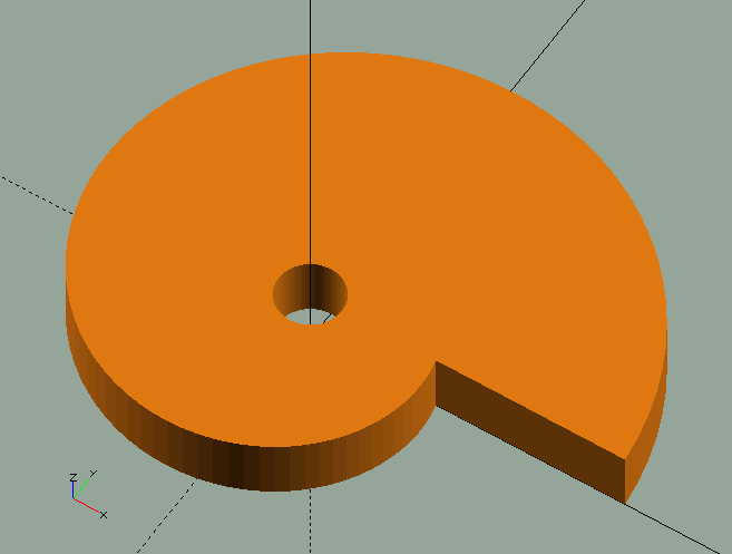
EOTWheel() generates a 'cam-wheel' with the EOT minutes (+/-) curve fitted between a given minimum and maximum radius.
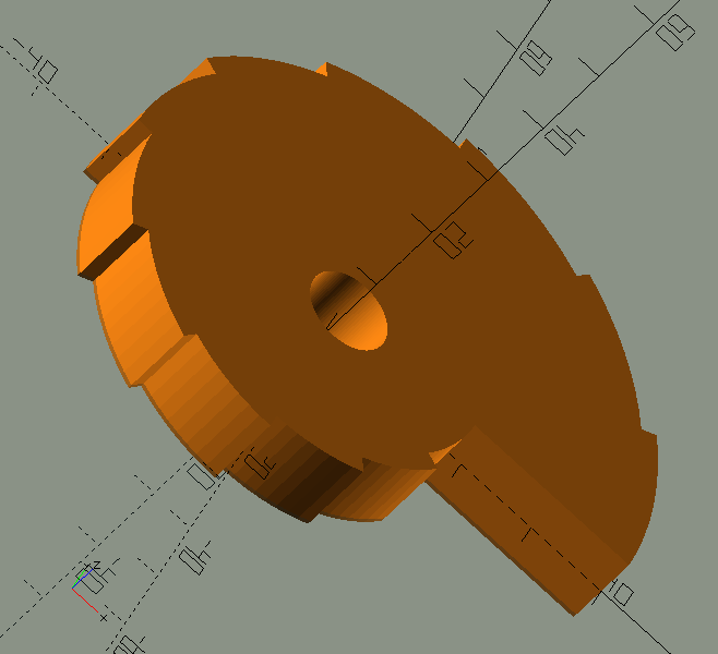
This cam can be used to move an indicator on an appropriate EOT scale. The first image (above), generated by EOTWheel(10,50,5,0.2,3); (image above) clearly shows the EOT relation, but the cam wouldn’t work very well in a real application, as the cam-follower will have some trouble following the steep slopes on the cam; the image to the right, generated by EOTWheel(40,50,5,0.2,3); would do a much better job. To allow for calibration of the mechanism, the EOT function publishes a number of values and radii, as well as the mechanical 'calibration factor' to help you achieve the desired results in your clock.
 It’s a nice 'complication'—the clock- and watch-maker’s word for unnecessary adornments and non-essential features—but for a number of reasons that, like EOT itself, really don’t matter a fig, pretty much useless.
The EOT wheel is generated with Jan. 1st on the positive x-axis, and it puts a small indicator diamond there if you let it, or perhaps you’d prefer a key-way of some sort… Finally, if you’d like to do a bit of reading, there’s a nice EOT article on Wikipedia.
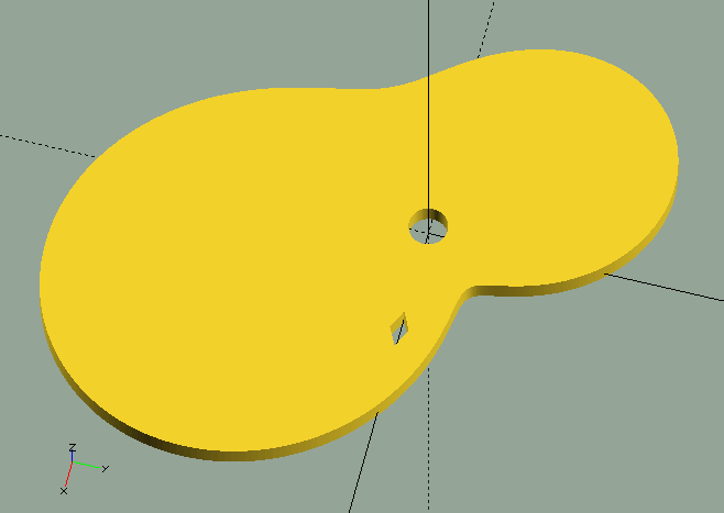
Snail()
Snail(OD,Steps,Drop,ID,Thickness)
-
OD, Dimension, largest outside diameter of the snail.
-
Steps, Integer, number of steps or 'drops' of the snail.
-
Drop, Dimension, height of the steps.
-
ID, Dimension, inside diameter, or spindle hole, of the snail.
-
Thickness, Dimension, thickness of the snail.
Snails are used together with racks to select the number of strikes.