The Buddha resides as comfortably in the circuits of a digital computer or the gears of a cycle transmission as he does at the top of a mountain.[1]
I Ain’t Done Yet!
|
|
This page is (still) under HEAVY construction. |
Things being worked on in The GHOUL—and to be documented when finished—are:
-
Internal gears
-
Bevel gears
-
Helical gears
-
Worm gears
-
Non-involute gears
In addition to that, some passages here need more clarification, there’s a lot that remains undone.
|
|
TLDR; Are you not here to learn, and do you know the PCD, Pressure Angle, Addendum and Dedendum as well as the number of teeth for your gear? Don’t waste your time: Go directly here (Do not pass Go. Do not collect $200.) |
Black Magic

You could easily be forgiven for thinking designing gears is just that, black magic. There’s an abundance of information on the wondrous wide web, but you may as well enter an engineering course, it’s going to feel like you did anyway after you sifted through all the information from here and there and put it all together, even if you concentrate on one system. However, for your inconvenience, there are several, incompatible systems, some easier, some not so much. Engineers,[2] do they talk to each other at all?
Many different tooth profiles and systems have been and are still in use. Two systems are prevalent today, both using the involute tooth form; the 'Module' based Metric Gears and the 'Diametral Pitch' based 'Inch Gears' of British origin but now often referred to as 'American'—probably thanks to that country’s[3] 'reluctance' to accept the superiority of the metric system. Then there are 'Circular Pitch' based systems, both metric and imperial, which are impractical from a machinist’s view, although in a 3D printing context the difficulties associated with them don’t present (as) much of a problem.
|
|
The GHOUL has functions and routines allowing you to work with module, diametral pitch, circular pitch or even—straight up—specify the pitch circle radius directly. |
There, sadly, are many, many more gear systems, all incompatible of course, but luckily much less popular, while some are—deservedly—confined to small niche applications. Non-involute tooth forms, cycloidal, trochoidal, ogival, composite and 'modified' involute systems, and I haven’t even started about 'stub' systems. As far as 'standards' go, they range from the familiar ANSI, BS, DIN and ISO to the 'Black Forest Standard' and 'Wickenburg', not to mention 'Wildhaber' and 'Novikov'. If you’re into wildly exotic stuff, get serious about watch- and clock-making; Pandora’s box can’t hold a candle to the horrors that await you there.
|
|
There’s a veritable treasure-trove of gear knowledge on the wondrous web; these are some of the better ones I’ve come across: Kohara Gear Industry Co. Ltd. All you need to know, in one convenient location. SDP/SI; bearings, belts and gears, don’t get lost… gear technology, a PDF archive of almost 40 years of one of the leading industry periodicals on gears, right at your fingertips. I suggest going back all the way to 1984, to read the 'back to basics' series. Best brew a cuppa before you sit down. Every day is a school day.[4] |
TLDR
To get things going—and make sure we’re on the same page—I’m going to go through a bit of a 'primer' first, for those who know nothing about gears but would like to have some understanding. Nobody—alive or dead—knows everything about gears, even knowing most of what there is to know would require significant study and a sizable library. I’m going to start at the beginning with this primer and it might be a bit TLDR and all that, so you can of course just skip it and go directly to the biscuits and gravy a.k.a.: reverse engineered gears and original design gears, if you like.
A Primer on Gears
Gears are—usually, but not always—used to make things turn slower or faster by using gears of different sizes, one driving the other. Fun Fact:[5] The smaller of the two is called the Pinion and the larger the Gear, regardless of which drives which.[6]
I’m using bold type on this page whenever I refer to names used in this image immediately below.
Gear Ratio
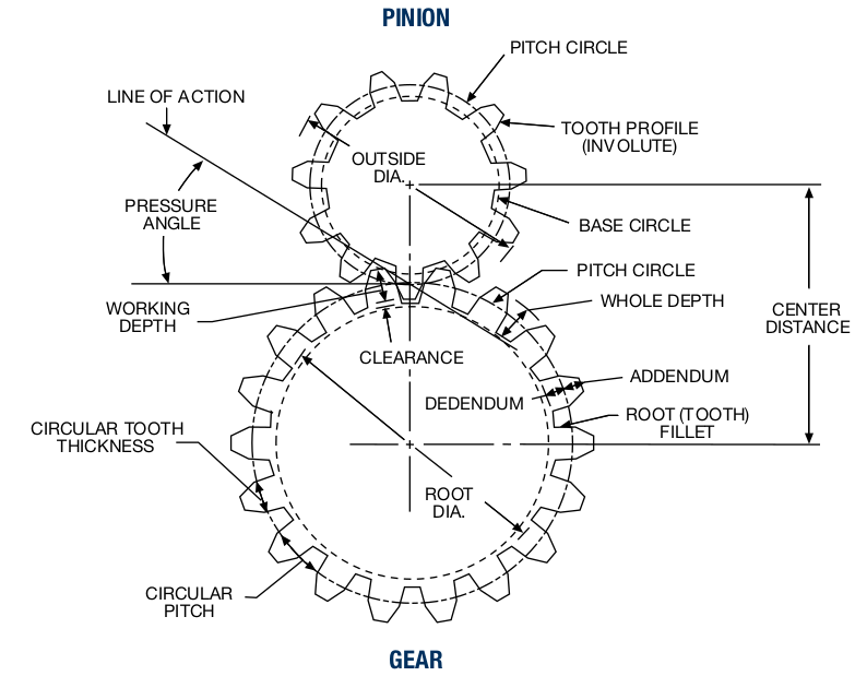
Let’s say you want something turning four times slower than something else, i.e., you want a gear ratio of 4 or 4:1. To achieve this, you use a pinion of 100 mm diameter driving a gear of 400 mm diameter. That should work. The pinion might have 28 teeth and the gear 112 teeth, for example. Now, where are these 100 mm and 400 mm diameters? They are called the Pitch Circles, and they lie—in standard gears—at roughly half the height of the teeth. We often refer to the pitch circle’s diameter, or PCD, and if you look closely, they’re just touching. That’s an important detail.
The gear ratio is the ratio of the rotations of the gears, but also the ratio of the pitch circle diameters, from which all other diameters are derived. It is also the ratio of the number of teeth of the gears. Gear ratios are given as the ratio of the driving rotations to the driven rotations. A 2.75:1 ratio means that the driving gear—the pinion in this case-- turns 2.75 times to make the driven gear turn once. Conversely, a ratio of 0.4 or 1:2.5 means that the driving gear only needs to turn 0.4 rotations to make the driven pinion turn once, or that one turn of the gear makes the pinion turn 2.5 times; they’re the same thing. Ratios bigger than 1 mean a speed reduction, and ratios smaller than 1 mean a speed increase.
|
|
You can click on the image above, it will open in a new tab so you have it handy when you’re reading something a bit further down the page and you’re thinking "The whatsit?" You’re welcome; I’m nice like that. |
Pitch, a divisive issue
If there’s a pitch circle, what’s the pitch? When we’re looking at gears, it’s a bit of a divisive issue. Pitch, to engineers, most often means 'spacing'—unless they’re aeronautical engineers[7]—and when you’re looking at round things, pitch means 'spacing around a circle'. Generally, that’s most easily expressed in degrees, but in the sense of gears and gearing, it is the spacing of the teeth around the gear on the pitch circle. In the image, it is labelled Circular Pitch, the true pitch of the teeth, an actual dimension, and there’s the rub.[8]
Because of that pesky π-relationship between diameter and circumference, using a rational circular pitch leads to irrational numbers for pitch circle diameter, and thus outside diameter and Center Distances between gears. Pocket calculators and computers have made life easier, but not too long ago, we used lookup tables and slide rules for these calculations, and irrational numbers were a major pain; gear design took days, not hours or even minutes… Apart from the involved calculations, the setup of tools for machining gears is also made more difficult by using circular pitch. Just be nice, and don’t.
There is, however, a way to get rid of the problem. Your local chapter of the fearless brotherhood of engineers decided to improve things by getting rid of the pesky π, so they could simply use nice rational numbers for teeth sizes and diameters, and then sneakily whisper 'times Pi' between their teeth… (See what I did there?)
However, in an effort to maintain the black magic image of gear design and keep lay-practitioners out of the workshop, how they improved the system depended on whether the brotherhood was of imperial heritage or continental, that is, the European continent. The latter decided to simply divide the pitch circle diameter PCD by the number of teeth on the gear Z, and called the resulting dimension Module. Sigh of relief. It always works with millimetres and Module2 or M2 simply means a pitch of 2×π mm. A bigger module means a bigger tooth and the number relates to an actual dimension. It’s a no-brainer, a simple 'slight of hand' that results in rational diameters and center-distances, and has greatly eased the pain of gear designers and machinists alike, all around the world:
\[ M [mm] = \frac {PCD [mm]}{Z} \] |
(1a) |
Those who used to work in Inches—and those who, despite strong indications that the metric system might be superior, still do—however, decided to be ornery and expressed pitch as the number of teeth per Inch diameter of the pitch circle. If that doesn’t immediately conjure a clear and unambiguous picture in your mind, don’t worry; you’re far from alone. They called it Diametral Pitch, and it’s not a dimension but a ratio and a DP3 tooth results in 3 teeth per π Inches on the pitch circle, making the circular pitch dimension in this case π/3 Inch. This also means that a higher diametral pitch means a smaller tooth. Here’s the relationship between DP, PCD and the number of teeth Z on the gear:
\[ DP [Teeth/Inch] = \frac {Z}{PCD [Inch]} \] |
(1b) |
Just to confuse things more, there actually is such a thing as 'Inch Module', but it’s—thankfully—rare and you may forget about it. Now. Really, please, forget it.
There you have it; one imperial system, one metric, both eliminating π, one actual dimension, one a ratio and of course they’re incompatible. An engineer’s dream and a machinist’s nightmare. Finally, if you’re curious; yes, diametral pitch and module have a relatively close relationship, although mutually unproductive:
\[ Module = \frac {25.4} {Diametral Pitch} \] |
(unimportant) |
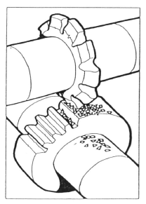 As we’ve seen, eliminating π means nice and easy rational numbers for diameters, and by standardising a list of modules, with as few as eight gear cutters and a
dividing head you can
'gash’[9]
out a gear (like in the image here) of any diameter in a hurry, and practically forget about
π.[10] A similar situation exists for DP based Inch gears, although there is no truly standardised list of diametral pitches that I’ve been able to find; the array of published lists that are supposed to be 'industry preferred sizes' all seem to differ in their preferences…
As we’ve seen, eliminating π means nice and easy rational numbers for diameters, and by standardising a list of modules, with as few as eight gear cutters and a
dividing head you can
'gash’[9]
out a gear (like in the image here) of any diameter in a hurry, and practically forget about
π.[10] A similar situation exists for DP based Inch gears, although there is no truly standardised list of diametral pitches that I’ve been able to find; the array of published lists that are supposed to be 'industry preferred sizes' all seem to differ in their preferences…
Since module relates directly to tooth-size, it makes sense that you’ll find fractional modules, like M0.5 or M0.8 used in small gears like the ones in a model airplane servo, or a mixer in your kitchen. Gears of M2 might be found in a car transmission and you might find big M10 or even M20 teeth in a moving mechanism of a bascule bridge.
The converse is true for DP gears. Instrumentation might contain gears of DP24 and higher, while a small winch could have DP12 gears. Teeth of DP8 or lower gears might be found in large equipment such as a trackhoe or a dozer.
As long as the gears of a set have the same module (or diametral pitch), they will mesh and work together, regardless of their diameters. The tooth shape changes with diameter, but the spacing on the pitch-circle is the same, and you’ll remember that the pitch-circles touch, so they’ll work. Caveat: this statement assumes a standard Pressure angle, Addendum and Dedendum, we’ll talk about those next.
Base Circle and Involute
Let’s look at a VERY important circle you’ll probably never know or specify the dimension of, the Base Circle. It’s important because it’s—literally—the base for the shape of the teeth. In a set of gears, the pinion and the gear have their own base circle, which is—of course—related to their pitch circle. There’s a straight line, the Line Of Action, tangent to the two base circles of the pinion and gear.
 The contact points (there are a few) between the teeth 'walk' along this line. Naturally, contact can only take place where this line lies between the two Outside Diameters. Also notice in the GIF here, how the 'next' contact starts, before the 'previous' contact is lost; this is a very important feature called overlap, the result of a Contact Ratio greater than 1, which is essential for the smooth operation of the gears. The forces on the teeth are also aligned with the line of action, because it is normal, i.e., perpendicular, to the tooth flanks along its entire length. In the image, the red dots are the contact points where the gold-coloured pinion drives the copper-coloured gear. The cyan dots are where the gear teeth touch the backs of the pinion teeth, giving 'support' so to say, and preventing the front sides from losing contact.
The teeth don’t fit tightly together, however; there is a little backlash, a.k.a. 'play', between gears to avoid excessive wear, jamming and, especially in metal gears, to allow for lubrication. The line of action is at an angle called—I’m assuming you still have the image open—the Pressure Angle, i.e., the angle at which one gear 'presses' on the other. Most gears are made with a pressure angle of 20°, but 14.5° used to be all the rage,[11] and sometimes 17.5° may be used, and sometimes… oh, more magic.
The base circle is also the basis for the involute, which is the shape of the tooth flanks. The involute is "a locus[12] formed by the end point of an imaginary line tangent to the base circle as the line rolls along the circle’s circumference", and in English: Imagine unwinding a piece of string from a drum, keeping it taut all the time; the end of the string will describe an 'involute curve', and this is the shape of the tooth flanks. By the way, I messed around for a long time getting that GIF there just right for you; the base circle is the grey disc, and I think the 'string' and involute are quite obvious.
 As gears—and their base circles—get bigger, the curvature of the involute becomes less and quickly approaches zero until, at about 135 teeth, the tooth shape becomes effectively that of a rack tooth, with straight flanks that are inclined at the pressure angle. The GIF on the right shows teeth forms for M1 teeth on gears from 10 to 140 teeth. At 10 teeth, there is a lot of undercut, and the teeth are weak. At 20, the teeth are well formed, and at 140 the teeth are practically rack teeth.
Finally, let’s have a look at Addendum and Dedendum. The addendum is part of the tooth outside the pitch circle, the dedendum lies inside the pitch circle. They are always sized in proportion to the module or DP, and in standard teeth they each are 1×M, giving the teeth a Working Depth of 2. Usually, there is a Clearance of 0.25×M at the root of the teeth. Inch teeth usually have an addendum and dedendum of 1/DP. In special cases, the addendum and dedendum may be shortened or extended, depending on the design goals. This can, for example, make gears with fewer teeth possible without risking undercut.
Gear design
Reverse engineering
You’re probably here to design a gear to replace one that broke in your mum’s mixer, or something like that. But… It’s tough to reverse engineer a gear. To measure a gear to find out what its original design parameters might have been is hard, even for the professionals, unless you know for sure that it was made in USA. Even then, it’s entirely possible that your gear wasn’t made with a standard tooth-shape, or center distance, for example and, finally, some wildly different and incompatible systems can look, and measure, almost identical, but not mesh properly… Sigh.
The problem is this; a gear design is the result of many parameters, and we can only measure a few dimensions, inaccurately. The result is a problem with many unknowns and only a few, inaccurate, knowns. If you paid attention in math or physics class, you know what that means; you’re in a 'whodunnit' with no workable leads.
If your gear is made of metal, it’s likely produced by machining technologies, and thus more likely to have a standard module or diametral pitch, unless it was die-cast—which is not unlikely for smaller gears—or you’re looking at a plastic gear, and either of those cases open up a whole box of exotic possibilities, I’m sorry to say.
Start by making the following assumptions—you have no choice—if you don’t know what these assumptions entail; don’t worry, like I said, you have no choice.
-
The gear is cut or produced with standard teeth, i.e.,
-
the teeth have an involute profile
-
the gears are of a standard module (or DP)
-
the gears have standard addendum and dedendum
-
-
The gears are of standard 20° pressure angle
-
The gear teeth do not have profile shift
Finding the Module
Now measure the outside diameter, OD of your gear, as accurately as you can; I suggest at least digital calipers, a micrometer is no overkill. Hopefully there’s no appreciable wear to throw the measurements way out… Next, count the teeth, Z and (in the continued hope that we’re looking at the standard addendum) you might just get the module M when you plug those numbers in here:
\[ M = \frac {OD}{Z+2} \] |
(2a) |
Since the standard addendum is 1×M, and the OD is equal to the PCD plus 2×addendum, this is simply equation 1a rewritten. If M worked out to a number in the list below, you’re in luck; your gear is—most likely—metric. Don’t hold your breath.
Standard Module: |
Series 1 |
0.1, 0.2, 0.3, 0.4, 0.5, 0.6, 0.8, 1, 1.25, 1.5, 2, 2.5, 3, 4, 5, 6, 8, 10 |
Series 2 |
0.15, 0.25, 0.35, 0.45, 0.55, 0.7, 0.75, 0.9, 1.125, 1.375, 1.75, 2.25, 2.75, 3.5, 4.5, 5.5, (6.5), 7, 9 |
Series 1 is preferred, you probably won’t find modules much below 0.5 or above 2 in home appliances and such. If you didn’t find your number in the list, measure the OD again (or convert it) in Inches and plug your numbers in this one:
\[ DP = \frac {Z+2}{OD} \] |
(2b) |
Now if it turns up in the list below, or not, you may have a gear that’s 'Made in USA'. I’m not sure whether to tell you to cross your fingers or simply abandon all hope…
Standard Diametral Pitch:[13] |
2, 3, 4, 5, 6, 8, 10, 12, 16, 20, 24, 32, 48, 64 |
Teeth with a DP6 or less are pretty large, but you might find stuff of DP64 in your house (remember, with DP it’s big number, small teeth).
|
|
Still no luck? Maybe you’re looking at a stub-toothed gear, which has addendums of 0.8; if your gear has less than 18 teeth, or works together with a much larger gear, there’s a good chance of stub-teeth. Go back, start at the beginning and, instead of Z+2 use Z+1.6, do both the M and the DP thing. |
|
|
What if you still didn’t find a good match? Scream. Blaspheme. Despair. You may be looking at profile shifted gears, non-standard gears, cycloid gears, or—quite likely—the margin of error is simply larger than the accuracy of your measuring instrument. Or, maybe it has a non-standard pressure angle. Even the pros end up here (small comfort). Crying helps, they say… |
Finding the Pressure Angle, or Module…
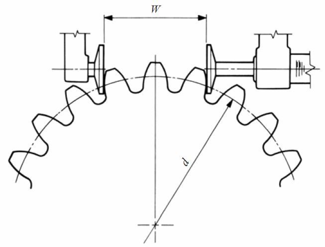
You can find the pressure angle, or indeed the module, by measuring the Base Pitch, i.e., the tooth pitch on the base circle. It doesn’t matter that you don’t know the Base Radius, because of the way involute teeth are formed, and we’re doing something sneaky; we’re not measuring base pitch directly, we’re deriving it from two other measurements…
You first measure the distance between 4 tooth flanks, then the distance between 3 tooth flanks; the difference is one Base Pitch BP. The image shows a disc-micrometer, and the least you should use is digital calipers, although you may struggle with those on small teeth; you’ll end up measuring the tips instead of the flanks, which is no good at all. You need to measure at the flank, so neither at the tip nor the root. If you have used (digital) calipers before, you know that just a little thumb pressure can throw the measurement by a few hundredths, especially when you measure with the tips, even more when the object you’re measuring is highly elastic (i.e., plastic), which is exactly what you’re likely to be doing here, and if you look at the list, you’ll see that a few hundredths is all that separates you from the next option; you’re basically groping for a catfish under a log in a muddy stream, but don’t let that discourage you… Look the BP up in the list below, check both systems and, to be sure, both pressure angles. Obviously, to find either module or pressure angle in this way, you must—in good gear-engineer fashion—assume the other. I know; black magic.
For the curious, and determined, here’s the math (assuming appropriate units for either method) for the tables below, α is the pressure angle:
\[ BP = M \times \pi \times cos \alpha \] |
\[ BP = \frac {\pi \times cos \alpha}{DP} \] |
(3a,b) |
| Module | Base pitch 20° | Base pitch 14.5° | Module | Base pitch 20° | Base pitch 14.5° | |
|---|---|---|---|---|---|---|
0.1 |
0.295213 |
0.304153 |
1.5 |
4.4282 |
4.56229 |
|
0.2 |
0.590426 |
0.608305 |
2 |
5.90426 |
6.08305 |
|
0.3 |
0.885639 |
0.912458 |
2.5 |
7.38033 |
7.60381 |
|
0.4 |
1.18085 |
1.21661 |
3 |
8.85639 |
9.12458 |
|
0.5 |
1.47607 |
1.52076 |
4 |
11.8085 |
12.1661 |
|
0.6 |
1.77128 |
1.82492 |
5 |
14.7607 |
15.2076 |
|
0.8 |
2.36171 |
2.43322 |
6 |
17.7128 |
18.2492 |
|
1 |
2.95213 |
3.04153 |
8 |
23.6171 |
24.3322 |
|
1.25 |
3.69016 |
3.80191 |
10 |
29.5213 |
30.4153 |
|
All dimensions in mm |
||||||
| Diametric Pitch | Base pitch 20° | Base pitch 14.5° | Diametric Pitch | Base pitch 20° | Base pitch 14.5° | |
|---|---|---|---|---|---|---|
2 |
1.47607 |
1.52076 |
12 |
0.246011 |
0.25346 |
|
3 |
0.984044 |
1.01384 |
16 |
0.184508 |
0.190095 |
|
4 |
0.738033 |
0.760381 |
20 |
0.147607 |
0.152076 |
|
5 |
0.590426 |
0.608305 |
24 |
0.123005 |
0.12673 |
|
6 |
0.492022 |
0.506921 |
32 |
0.0922541 |
0.0950477 |
|
8 |
0.369016 |
0.380191 |
48 |
0.0615027 |
0.0633651 |
|
10 |
0.295213 |
0.304153 |
64 |
0.0461271 |
0.0475238 |
|
All dimensions in Inch |
||||||
What’s next
After the painful exercises outlined above, you now—hopefully—have the parameters you need to design a nice and shiny new copy of your broken gear:
-
Outside Diameter
-
Module or Diametral Pitch
-
Addendum and Dedendum (Standard or Stub)
-
Number of teeth
All we need now is the Pitch Circle diameter, PCD, which follows simply from equation 1a and equation 1b. Never mind, I’ll repeat them:
\[ PCD = M \times Z \] |
\[ PCD = \frac {Z}{DP} \] |
(1a,b) |
and we’re off to the races. There, that link you just passed, click it!
Original design
To design a gear from scratch, you’ll need the following parameters to satisfy The GHOUL’s gear generating functions' needs:
-
Pitch Radius
-
Number of teeth
-
Pressure Angle - defaults to 20°
-
Addendum - defaults to 1×M
-
Dedendum - defaults to 1×M
-
Clearance - defaults to 0.25×M
Of course gears come in pairs—usually, but not necessarily—and the gear ratio for your pinion and gear pair is probably the first thing that is known and fixed (and you’ll need two sets of the parameters above).
Then, there are some considerations you should take into account.
-
How much room is available
-
How much power or force must be transmitted
-
Is the center distance of the gears a choice or a given
Now you have to decide how to shuffle the parameter values to achieve the optimum gears for your application. You can achieve the same gear ratio Z1:Z2 with any number of teeth, but within the available room, it becomes more important that the teeth are strong enough to withstand the forces on them, so there will be a minimum tooth size, i.e., a maximum number of teeth that satisfies the design.
|
|
This is not an engineering course. I’m not going into forces, material strength, heat dissipation, wear properties, acceptable rpm, life expectancy &c. Sorry. Nah, I’m not. But I did give you some links to some
excellent resources. Ultimately, if you want to do the things an engineer does, you first have to become an engineer…[14] |
So, let’s work through a simple example:
An example in module gears
Given these design requirements:
-
Gear ratio 3:1 (Input rotations : Output rotations)
-
Max combined diameters 100 mm
Let’s say we restrict ourselves to an exact dimension and use up all the room we’ve got. We have 100 mm for the two pitch circles plus two times the addendum. If that’s not immediately clear; have a look at this image again, it opens in a new tab. We know the (standard) addendum equals the module, and we also know that the pitch circle diameter equals the module times the number of teeth. With the ratio of 3:1, we know that the combined pitch circle diameters are equal to four times the pinion pitch circle diameter, and the total number of teeth is four times the number of pinion teeth Z1, so we can write a simple case specific formula:
\[ 4 \times Z_1 \times M + 2 \times M = 100 mm \Rightarrow 2 \times Z_1 + 1 = \frac {50}{M} mm \Rightarrow M = \frac {50}{2 \times Z_1 + 1} mm \] |
(5) |
Since Z1 can only be integer, and there’s a fixed list of modules, this doesn’t give many solutions. Z1 = 12 with M = 2 is a solution, but 12 teeth is a no-go[15]. The next solution is Z1 = 62 with M = 0.4, a possibility perhaps, M0.4 teeth are about 1.2 mm thick at the root. But do we have to restrict ourselves this much? The answer is of course no. There are two options; we can be flexible in diameter and center-distance, or shift the tooth profile. We’re not ready for profile shift yet, but how about this:
| Module* | Z1 | Z2 | Outside dimension | Between centers dimension |
|---|---|---|---|---|
1 |
24 |
72 |
98 |
48 |
0.8 |
30 |
90 |
97.6 |
48 |
0.6 |
41 |
123 |
99.6 |
49.2 |
0.6 |
40† |
120 |
97.2 |
48 |
* Given the maximum overall dimension of 100 mm and gear ratio of 3:1; the Module is chosen, the rest follows. |
||||
|
|
Do you see how we’re only getting nice rational numbers here? No horrible never ending fractionals. That’s because of the brave brothers of your local engineering association and their decision to chuck π in the ditch. Since we never[16] measure circumferences, who cares what they are, and now we’re getting nice, easy diameters to measure. That makes machining a breeze. Well, at least when you’re setting things up on your Bridgeport. Of course, you’re 3D printing and you don’t care, but at least now you know why π had to go. |
Since we’re throwing math around a bit here, here’s the shortcut:
\[ Z_1 = \Biggl \lfloor \frac { \frac {Max\ Dimension}{Module} -2 }{ 1 + Ratio } \Biggr \rfloor \] |
(6) |
The funky 'bottom-hook-only-square-brackets' in equattion (7) mean floor(). Here’s the OpenSCAD code:
// Z1=floor(((MaxDimension/Module)-2)/(1+Ratio));

Module=1;   // chosen value from standard
Ratio=3;  // chosen value (input rotations per ONE output rotation --or-- Z2/Z1 )
MaxDimension=100;  // chosen value
Z1=floor(((MaxDimension/Module)-2)/(1+Ratio));
Z2=Z1*Ratio;
CenterDistance=Module*(Z1+Z2)/2;
MaxDim=Module*(Z1+Z2+2);
Print(["Module= ",Module," Z1= ",Z1," Z2= ",Z2," MaxDim= ",MaxDim," CenterDistance= ",CenterDistance]);

ECHO: "Module= 1 Z1= 24 Z2= 72 MaxDim= 98 CenterDistance= 48"The GHOUL’s gear functions
InvoluteGear()
InvoluteGear(Module, Teeth, Addendum=1, Dedendum=1.25, Shift=0, PressureAngle=20, Allowance=0, Title="Gear")
-
Module, scalar, 'dimension' of the tooth size.
-
Teeth, integer, number of teeth of the gear.
-
Addendum, scalar, factor of the Module, defaults to standard, i.e, 1.
-
Dedendum, scalar, factor of the Module, defaults to standard, i.e, 1.25.
-
Shift, scalar, amount of profile shift (in 'Modules').
-
PressureAngle, scalar, degrees, defaults to standard, i.e, 20.
-
Allowance, scalar, additional production clearance, defaults to 0.
-
Title, string, identifier for console output, defaults to "Gear".
For the meaning of the terms used here, see the documentation
above. InvoluteGear.scad contains a function InvoluteGear() which returns an array of vertices forming the outline of the requested gear, ready to be post-processed or used directly in a polygon(). It also contains a module that takes the same parameters and generates the gear polygon directly, to be used with linear_extrude() &c.
The parameters Addendum, Dedendum and Shift are expressed as fractions or multiples of the module of the gear. The module is equal to:
\[ Module = \frac {Pitch\ Circle\ Diameter}{Number\ of\ Teeth} \] |
(8) |
Generally, in the
gear design process, you decide on a maximum dimension and a suitable module or 'tooth size' for your gear, the number of teeth follows from those requirements and these parameters fed into InvoluteGear() to generate a gear.
The module is a design choice, modules M<1 are mostly used in instruments and small (household size) mechanisms, modules 1<M<3 may be found in fractional horsepower transmissions, and 3<M are found in multi-horsepower applications.
Assuming a standard addendum size of 1×Module, the PCD follows from the available ODmax as follows:
\[ PCD = \bigl \lfloor OD_{max} - 2 \times Module \bigr \rfloor \] |
(9) |
In case you missed it earlier, the funky 'bottom-hook-only-square-brackets' mean floor().
Aliases
InvoluteGear() has a number of aliases, for your convenience. They all take exactly the same parameters, except for the first; things should be clear from the calls:
InvoluteGearPCD()
InvoluteGearPCD(PitchCircleDiameter, Teeth, …) to make gears by directly specifying the PCD.
All of the alias functions—in good old The GHOUL fashion—also have a module 'companion', and all of them work in your native units, be that mm, inch or fathoms (Arrr!), whatever floats your boat so to say—although a diametral pitch in mm would be a bit silly…
InvoluteGearTooth()
InvoluteGearTooth(Module, Teeth, Addendum=1, Dedendum=1.25, Shift=0, PressureAngle=20, Allowance=0, Title="Gear")
-
See
InvoluteGear(), above for the parameter legend.
This is not really a user function, but you never know. InvoluteGearTooth() returns an array of vertices for a single gear-tooth. It calls the involute and trochoid generating routines and concatenates the root- and flank-curves into an array of vertices of a complete gear-tooth shape. You could use the array to make a polygon of a single tooth, but I don’t know why you would.
There are no alias functions for InvoluteGearTooth(), it really wouldn’t make much sense, but if you’re desperate for them, just copy what I did in InvoluteGear.scad.
Involute()
Involute(BaseRadius, TipRadius, StartRadius)
Involute() returns the vertices of an involute curve for the given design parameters. This is not really a user function…
Rack()
Rack(Module, Teeth, Addendum=1, Dedendum=1.25, Shift=0, PressureAngle=20, Allowance=0, Title="", Tip=0.2, Root=0.2, Support=1)
-
See
InvoluteGear(), above for the parameter legend. -
Tip, scalar, tip-radius, in 'Modules'.
-
Root, scalar, root-radius, in 'Modules'.
-
Support, scalar, dimension, thickness of the rack-base.
Rack() generates a rack for the given design parameters. There is a module as well as the function. The module generates the polygon(), the function returns the array of vertices.
RackTooth()
RackTooth(Module, Addendum=1, Dedendum=1.25, Shift=0, PressureAngle=20, Allowance=0, Title="", Tip=0.2, Root=0.2)
-
See
InvoluteGear()andRack(), above for the parameter legend.
RackTooth() returns an array of vertices for a rack-tooth for the given design parameters.
UnderCut()
UnderCut(BaseRadius, RootRadius, PitchRadius)
-
See
InvoluteGear(), above for the parameter legend.
UnderCut() returns the vertices for the part of the tooth flank curve for the given design parameters that lies inside the base circle. As gears get larger, the difference between the outside radius and the base circle radius also grows, and at a certain point the working height of the tooth (addendum plus dedendum) fits between the OD and the base circle of the gear. At this point, the tips of the meshing rack (or gear) no longer reach past the involute and we are free to use any shape for this part of the tooth flank and root and, obviously, a simple radius fillet makes the most sense.
|
|
There may (read: will) be more functions in the pipeline: I ain’t done yet! |