I just toured around looking for fractals, and when I found something that had a scaling geometry, I would ask the folks what was going on - why they had made it that way.
Scalable Vector Graphics
SVG is 'just another parametric way to describe 2D shapes', but it’s quite elegant in it’s elementary simplicity. It has always — i.e., since I started working with OpenSCAD — struck me as natural that there should be an SVG implementation in OpenSCAD, and this library provides just that. If you’ve ever looked at some clipart or image on the old interwebs, and thought 'That would be nice, embossed on my 3D-printed such-and-such design…', here’s some good news for you: As long as your image is an SVG (and there are very many in the public domain), the GHOUL will take it’s 'd' path property, a path-string, and turn it into a polygon for you.
|
|
The closing sentence of the preceding paragraph contains the main caveat you should keep in mind when using this library. The SVG specification contains a massive number of elements with a huge number of properties. Have a look here if you wish to be depressed, but because OpenSCAD isn’t Inkscape, or a web-client, this library only implements what’s of real interest to us as OpenSCAD users: the 'd' property which defines a path to be drawn, to be made into a polygon, to have another shape extruded along, as a baseline for text, or… You know what they say about the sky.[1] |
Let’s have a look at what the specification says:
If that doesn’t remind you of the
OpenSCAD manual entry for polygon(), well, I guess you might not have read the entry…
Grab an SVG image, open it in your text editor, copy the d property of the path element, paste it in The GHOUL’s SVG() call, and there you are. You like the fontawesome icons? Same thing goes. With a little effort you can convert any 'ttf' font into SVG glyphs,
offline
or
online. Then you can grab any icon or character from the font and do what you want. Scale it, skew it, stretch, mirror, extrude, change and adopt it to exactly what you need. Grab a sub-path, combine letters, paths, shapes… You get the drift.

The GHOUL’s SVG library will correctly parse and process successive smooth cubic and quadratic Bézier curve commands in the SVG path — I’m kind of proud of that — whether they are relative or absolute. Arcs are a breeze. I haven’t stumbled on a valid path that this library hiccups over, but if you do, I’d very much like to know. I’ll leave you to it, you’ll be a while ;-)
Since I mentioned images and fonts, you may know about the different coordinate systems used by the SVG specification for these two different applications:
|
|
Unlike standard graphics in SVG, where the initial coordinate system has the y-axis pointing downward, the design grid for SVG fonts has the y-axis pointing upward for consistency with accepted industry practice for many popular font formats. |
What? You mean standard SVG graphics are working with screen coordinates with the origin in the top-left corner? Yep. That’s what they mean. But here’s the really great news: not always. When describing fonts, the coordinate system has the origin in the bottom-left corner, with the X-axis and Y-axis where you normally find them. And not all images use the screen coordinates, some use the regular coordinate system. Right? SM#H =/
The GHOUL SVG library takes all that in it’s stride: through the SVG_Coords parameter, the different coordinate systems used by SVG images and fonts are all parsed and displayed correctly. More about that later.
An intro to the SVG Path
Before we dive into the library proper, let’s have a quick basic run-through of the SVG path element, the d property, and some of the commands that make up a path. An SVG image or font description is a text file, just like the OpenSCAD .scad files, but SVG uses the .xml standard which uses tags much like a .html file does. When you open an SVG .xml file, you will normally find one (in image files) or several (in font files) tags like this:
<path d="M 0 0 L 100 0 L 100 100 l -100 0 z"
        fill="red" stroke="blue" stroke-width="5" />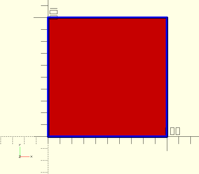
What we’re interested in is the path data, the d="M 0 0 L… assignment; the d property of the path element. In an image, this should be a single string, containing all the subpaths and commands. It’s important to remember that the subpaths influence each other with difference()-like operations when they overlap or fall within each other.
The path in the above code snippet describes a simple square, drawn in blue lines with red fill. The SVG specification for paths includes properties like 'stroke' and 'fill' for colors and 'stroke-width' &c. We are only generating polygons and stroke and all the other attributes are not implemented in this library. Think of the implementation here as SVG with stroke 'off' and fill always 'on'. If that makes you sad, ditch OpenSCAD and get Inkscape.
The call for that same path, using this library, would look like the first one in the code snippet below (note that the string is copied literally), the others are variations you may come across, they all work; SVG() is smart when it comes to interpreting the path-string, but I think the first one is much more easy to read, and what do we save by omitting spaces…
SVG("M 0 0 L 100 0 L 100 100 l -100 0 z");

SVG("M0 0L100 0L100 100l-100 0z");
SVG("M 0,0 L 100,0 L 100,100 l -100,0 z");
Let’s have a quick look at these commands:
| M |
moveto (absolute) [0,0] Although the SVG specification states that, without an initial moveto command, the polygon is drawn beginning at [0,0], it behooves a good programmer to explicitly state this. The library will enforce this by prepending this command to strings where it is missing. |
| L |
lineto (absolute) [100,0] &c. Draw a line to this coordinate. |
| l |
lineto (relative) [-100,0] Draw a line to this relative coordinate (from the current point). |
| z |
closepath This command is in the SVG specification as a line may be drawn and not a polygon. At this moment this is not implemented by this library, as a closed path is implicit in the OpenSCAD |
There are several more commands for horizontal (H/h) and vertical (V/v) straight lines, arcs (A/a), circular and elliptical — yes, I know… — and cubic (C/c) and quadratic (Q/q) Bézier curves. The curves can be 'smooth', in which case they mirror the previous curve’s last control point in the current point (the end-point generated by the previous command), they are the smooth cubic (S/s) and the smooth quadratic (T/t) Bézier curves. Here’s a primer on Bézier curves if you’re not familiar with them, they’re simply marvellous.
All commands have an uppercase and a lowercase variant, indicating that they refer to absolute or relative coordinates.
There is lots of information available online, even though much is discussed in the commands below, I suggest you read one of these pages from W3C or Mozilla or this really neat illustarated guide on css-tricks before you start writing your own paths. Brew a good jug of strong Java before you do, they’re a bit of a read, but very useful… I’m going to repeat that for the 'scan and go' type of visitor here:
|
|
WOULD-BE PATH WRITERS, READ A GUIDE FROM EITHER: W3C or Mozilla or this cool one at css-tricks. |
SVG() also accepts a 'path-array' instead of a 'path-string'. This makes it much easier to integrate variables and parameters into the path. The Thread() module, through ThreadData() makes use of that. An example of this is:
    SVG([
        "M",_Height/2,_Height,
        "A",_Height,_Height,0,0,1,_Height*_MaD,-_Pitch/2,
        "L",_Height*_MiD,-_Pitch/2,
            _Height*_MiD, _Pitch/2,
            _Height*_MaD+_ClrR, _Pitch/2-_ClrA,
        "A",_Height*_MaRr,_Height*_MaRr,0,0,1,_Height-_TaperRm,_Pitch/2,
        "L",_Height/2,_Pitch/2
    ])
As you can see from the example, the array consists of the commands as strings, followed by their parameters as normal scalar values. Jolly useful.
Using The GHOUL’s SVG library
Let’s have a look at the one and only call you’ll ever need to make to use SVG graphics in OpenSCAD:
SVG()
SVG(PathString,SVG_Coords=false,Size=[1,1]
-
Pathstring, string, any valid SVG path-string,OR a 'path-array' as discussed above.
-
SVG_Coords, Boolean, if true, the Pathstring will be interpreted as an image path, with the positive Y-axis pointing down. If false, the Pathstring will be interpreted as a font path, with the positive Y-axis pointing up.
-
Size, vector, 2D scaling vector with x- and y-scaling factors.
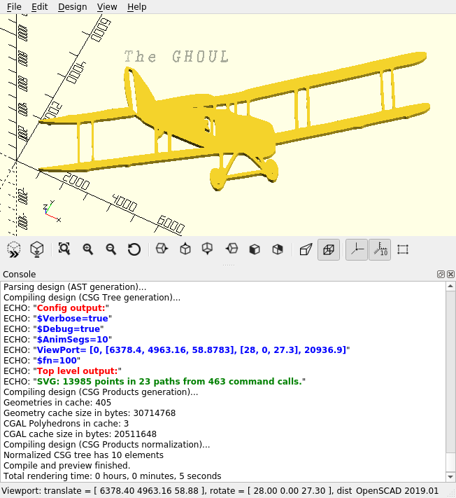
SVG() takes a valid SVG path element d property, the PathString, parses the string, generates the points along the paths, and returns the points and paths in the format required by the OpenSCAD polygon() call. If $Verbose is set to true, it will echo the point, path and command count in the console, as seen in the image here. (If your eyes are like mine, )
|
|
If you’re wondering how to get such pretty console output; since 2021.1, the console no longer renders html font tags, so the beautiful colours and bold print you see here in the images is a thing of the past. Apparently that’s what they call 'improvement'… SM#H :-[ |
Like many other routines in The GHOUL, SVG.scad contains both an SVG() module and a function. The function returns a pair of lists [PolyPoints,PolyPaths], PolyPoints contains all the polygon points in a single list, and PolyPaths contains — nomen est omen — list(s) of the points of the path(s) for the OpenSCAD polygon() call. The module simply takes the result from the function and generates the polygon(s) for you, no hassle. The main reason for the separate function is that it allows you to post-process the resulting points-list.
You can, for example, make a quick path to use for a rotate_extrude() call:
rotate_extrude(angle=180,convexity=10)
SVG("M 0 0 L 4 0 C 2 5 5 2 5 6 Q 5 8 2 8 h -2 v -0.5 h 2 Q 4.5 7.5 4.5 6 C 4.5 2.5 1.5 5 3.5 0 ",true);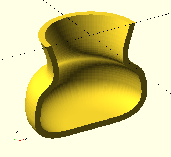
How nice is that? Because SVG is so blissfully simple, and makes great use of smooth cubic and quadratic Bézier curves, it allows you to quickly create smooth paths like this in a very short time, off the top of your head, no math, no notes, no prep, no sketches. Just close your eyes, see the shape, write the path. I think, as a kind of 'top layer' it makes the GHOUL’s Bézier curve library much more accessible and easier to use.
There. That’s it, SVG() is the only call you’ll ever need to make to use SVG paths in OpenSCAD.
And, there’s more—but we can’t do this all day… ;-)
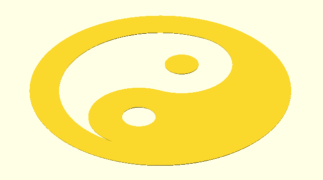
SVG() is so easy to use and versatile, and with the ability to describe complex shapes in a single string, doesn’t it seem natural to have indexable or searchable shape collections, defined in arrays, that can be easily called like:
SVG_Shape(FavIcons,"YinYang");SVG_Shape() does exactly that, simple, convenient. Create collections of shapes you regularly extrude, emblems you emboss on objects &c.
SVG_Shape()
SVG_Shape(Collection,Name,Size=[1,1],Center=false,Home=false)
-
Collection, array variable name, i.e., a collection name.
-
Shape, string, SVG-shape record name, i.e., it’s identifier.
-
Size, tuple, scaling factors for the shape.
-
Center, Boolean, center shape on origin.
-
Home, Boolean, place the shape at 'home' in the first quadrant.
It’s easy to have all your SVG shapes in one collection, or define different classes in separate collections. /TheGHOUL/Lib/SVG/Shapes/ directory contains a collection called FavIcons.scad, mostly as an example, you’ll be making your own, and you can easily add a directory to The GHOUL to keep personal collections &c. separate from the rest of The GHOUL.
Collections of shapes are arrays of records like:
    CollectionName=[
        ["ShapeName","SVG_Path",SVG_Coords,"ID", ... ],
        [...]
    ];
SVG_Shape() expects each shape record to contain at least these elements:
-
Name, string, name of the shape or icon
-
SVG_Path, string, a valid SVG path-string
-
SVG_Coords, Boolean, flag, use SVG coordinates if 'true'
You can give the record as many additional elements as you like…
SVG_Shape() searches the array for the record containing the identifier, then takes the pathstring from that record and generates the polygon.
It uses the SVG_Coords Boolean to switch to SVG coordinates, i.e., 'upside-down', if it is true. Like many of The GHOUL’s routines, SVG_Shape.scad also contains a function SVG_Shape(), which returns a 'polygon-tuple' like [points,paths].
When SVG_Coords is true, the shape is generated in the fourth quadrant. The Home and Center Booleans are available to move the shape, either in the first quadrant and touching the X-axis and Y-axis, or centered on the origin. The Shape’s size is published to the console if $Verbose is true (See Config.scad).
SVG_Glyph()
SVG_Glyph(Font,Character,Size=[1,1])
-
Font, string, font identifier.
-
Character, string or unicode, glyph identifier.
-
Size, tuple, scaling factors.
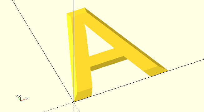
SVG_Glyph() uses font definition files that are stored in TheGHOUL/Lib/SVG/Fonts/ and which are loaded by Lib_SVGFonts.scad.
The font definition file contains a single array, the name of which is the font-identifier Font. If the required character is one of the 'printable characters' (Ascii 33-126), simply use the character itself as Character, i.e. the string "A" will generate a capital letter 'A' &c. For any of the characters that are not in that Ascii range, the four-digit hexadecimal UniCode is used as the identifier, e.g. "215E" would yield '⅞'.
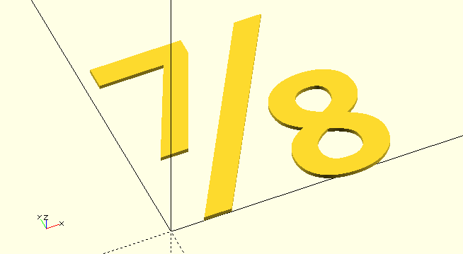
SVG_Glyph(OpenSans_SemiBold,"215E")The next development for the SVG library will be string support with proper kerning. The font-definition files already contain the kerning tables, but right now I’m a little preoccupied with developing routines to bevel any complex polygon(), it’s a bit of a "Squirrel!" moment.
|
|
SVG_Glyph() is not yet quite as polished as I’d like, expect it to change it’s behaviour some time in the future, also see 'TODO' comments in SVG_Glyph.scad.
|
SVG path commands
For those wanting to write their own paths, this is an intro to the commands and their syntax. Also check out the links to online information above.
|
|
This SVG library is more than reasonable with regards to tolerating garbage in the path-string that it’s being fed, but it draws the line at /newline and /return characters. It will throw a wobbly, and the proverbial matter will hit the rotating air-mover. I can live with that, and you will have to as well, they have no place in an SVG path to begin with, but they are often found inside pathstrings in xml definitions of SVG images and fonts, so: Be nice. Write (or copy and edit) clean, well parsed path-strings without newlines or returns. It’s not too much to ask: remove /newline and /return characters, most other garbage can stay. |
A/a
A/a (Rx Ry XRot LAF SF Nx Ny)+
-
Rx,Ry,Nx,Ny, radii, i.e., major and minor semi-axes and next point coordinates, see convention.
-
XRot, angle, rotation of the ellipse. Rotation, in the SVG specification as well as The GHOUL convention, is always positive from the positive X-axis towards the positive Y-axis. If SVG coordinates are in force (Y-axis pointing 'down'), positive rotation results in clockwise movement 'on the canvas'.
-
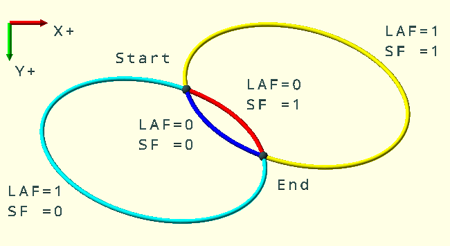
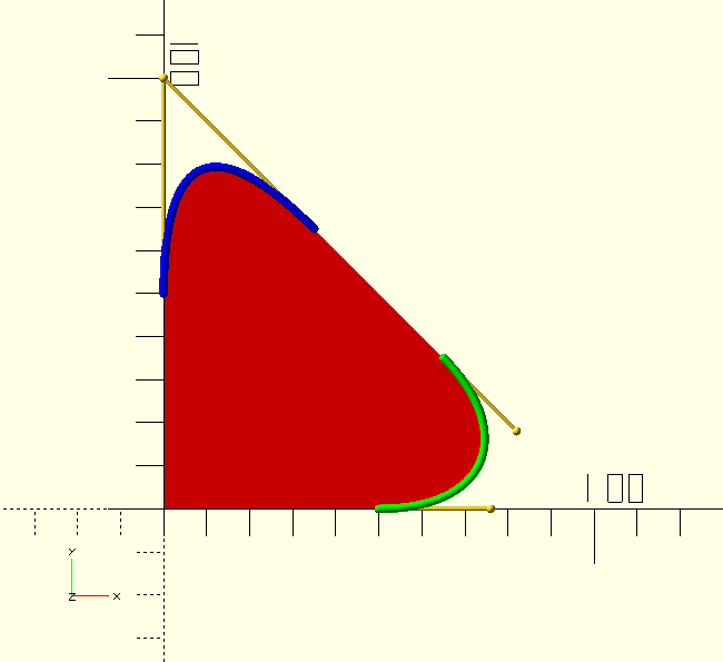
LAF, SF, Large-Arc-Flag and Sweep-Flag, 0/1, looking from [Px,Py], the current point, to [Nx,Ny], the next point, the Sweep Flag determines arc direction: SF=0 yields a counter-clockwise arc, and SF=1 yields a clockwise arc. The Large Arc Flag determines which of the fitting arcs is drawn, LAF=0 yields the smaller and LAF=1 yields the larger arc. See the accompanying image.
Multiple parameter sets can be given to the same A/a command, and are processed successively according to the SVG specifications.
Don’t lose track of the current point when writing relative arc commands with multiple parameter sets…
//               Large Arc Flag --v v-- Sweep Flag
color(BLU)SVG("M 0 0 A 150 100 20 0 0 100 100z",true); // small ccw
color(CYN)SVG("M 0 0 A 150 100 20 1 0 100 100z",true); // large ccw
color(RED)SVG("M 0 0 A 150 100 20 0 1 100 100z",true); // small cw
color(YLW)SVG("M 0 0 A 150 100 20 1 1 100 100z",true); // large cw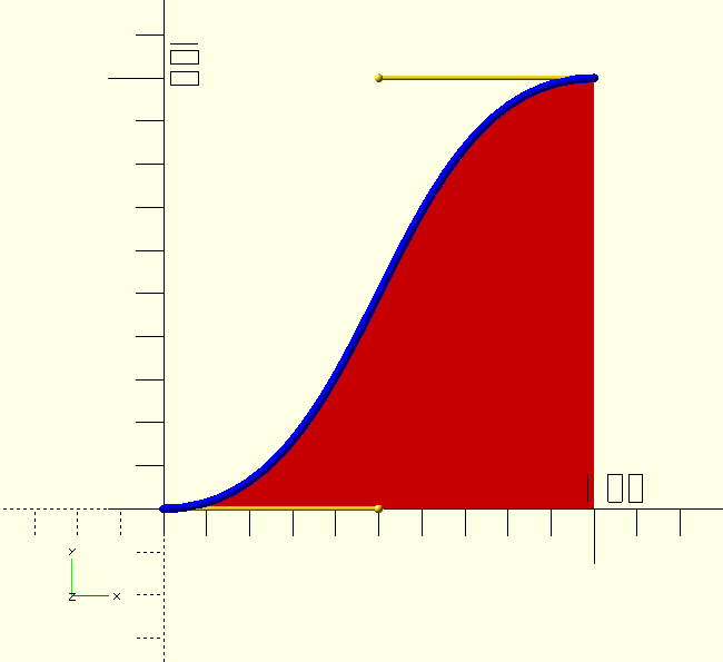
C/c
C/c (C1x,C1y,C2x,C2y,Nx,Ny)+
-
C1x,C1y,C2x,C2y, control-point coordinates, see convention.
-
Nx,Ny, next point coordinates, see convention.
C/c accepts multiple parameter sets, but it is usually followed by a smooth curve command S/s or T/t, as that makes much more sense.
Nonetheless, multiple sets are parsed and processed correctly according to the SVG specifications.
SVG("M 0 0 C 50 0 50 100 100 100 v -100z");The cubic Bézier curve is fully described by four points; a beginpoint, two control points and an endpoint. In SVG terms, the 'current point' is the beginpoint and the 'next point' is the endpoint, the controlpoints determine the direction and shape of the curve at the endpoints.
|
|
The cubic Bézier curve gives you total control over the direction of the curve at the endpoints. If you want to have several curved sections in succession, start with a cubic curve, then continue with smooth cubics S/s or smooth quadratics T/t. The smooth curves give you full control over the direction of the curve at the endpoint as well.
|
|
|
If you’re completely new to Bézier curves, please have a look at the GHOUL’s Bézier curve library first. |
H/h
H/h (Coord/Dist)+
-
Coord/Dist,
H/honly takes one parameter, which has two different meanings, Coordinate or Distance, depending on whether the command is absoluteHor relativeh. In an absolute call it draws a line to the point with X=Coordinate and Y=Py. In a relative call it draws a line to the point with X=Coordinate+Px and Y=Py.
It is possible to give H/h multiple X-coordinates or distances, but since it’s a 1D command, that doesn’t seem to make a lot of sense. Either way, the library will deal with them correctly, according to the SVG specifications.
The code snippet below contains both the absolute and the relative call that would result in the accompanying image.
SVG("M 20 0 H 100 Q 60 100 20 0z") // absolute
SVG("M 20 0 h 80 Q 60 100 20 0z")  // relative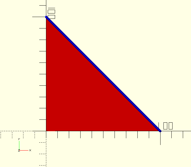
L/l
L/l (Nx,Ny)+
-
Nx,Ny, next point coordinates, see convention.
Multiple coordinates can be given to quickly draw a complex shape.
The code snippet below contains both the absolute and the relative call that would result in the accompanying image.
SVG("M 0 0 H 100 L 0 100z")
SVG("M 0 0 H 100 l -100 100z")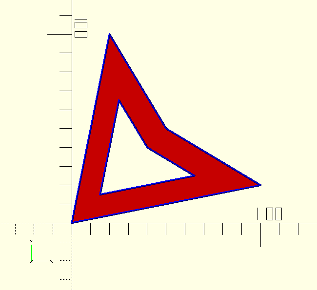
M/m
M/m (Nx,Ny)+
-
Nx,Ny, next point coordinates, see convention.
The SVG M/m move command is a double edged sword; when given more than one set of coordinates, the first coordinates are interpreted as a 'moveto' command and all subsequent coordinates are interpreted as a 'lineto' L/l command. The code snippet below contains the call that would result in the accompanying image.
SVG("M 0 0 100 20 50 50 20 100 M 15 15 65 25 40 40 25 65z");In an absolute call, the current path is terminated with the current point as it’s endpoint, and a new path is started at the next point coordinates. In a relative call, the current path is terminated with the current point as it’s endpoint, and a new path is started at the current point plus the next point coordinates.
Q/q
Q/q (Cx,Cy,Nx,Ny)+
-
Cx,Cy, control-point coordinates, see convention.
-
Nx,Ny, next point coordinates, see convention.
The SVG Q/q command yields a quadratic Bézier curve, it accepts multiple parameter sets, but it is usually followed by a smooth curve command S/s or T/t, as that makes much more sense.
Nonetheless, multiple sets are parsed and processed correctly according to the SVG specifications.
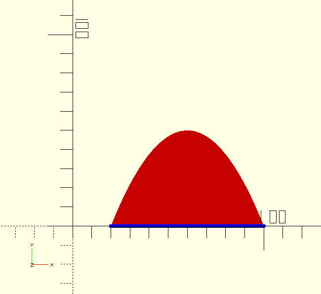
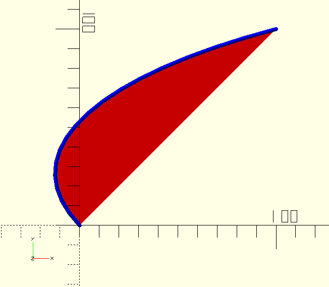
The code snippet below contains the call that would result in the accompanying image.
SVG("M 0 0 H 100 L 40 60 Q 0 100 0 50 V 0z");|
|
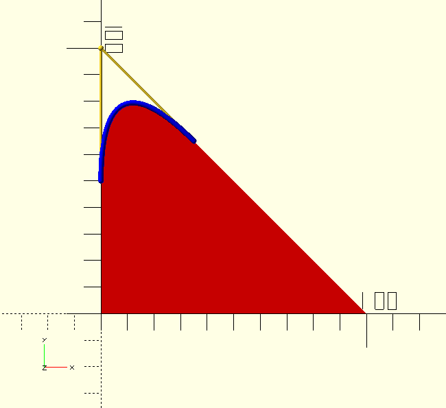
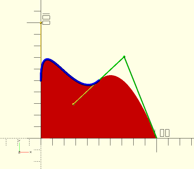
 The quadratic Bézier curve is very well suited for curved corners.
Finish the straight sections either side of the corner at equal distances, put the quadratic curve’s controlpoint on the intersection of the lines and Bob’s your uncle: a perfectly smooth rounded corner like the blue curve in the image.
The quadratic Bézier curve is very well suited for curved corners.
Finish the straight sections either side of the corner at equal distances, put the quadratic curve’s controlpoint on the intersection of the lines and Bob’s your uncle: a perfectly smooth rounded corner like the blue curve in the image.The corner will not have a circular shape, i.e., not a constant radius. To closely mimic a circular shape, use a cubic curve, and put the control points at 0.552 of the distance between the line ends and the corner point like the green curve in the image. Even putting the controlpoints simply halfway will give a reasonably circular shape to the corner. Also see Bézier circle approximation. |
|
|
If you’re completely new to Bézier curves, please have a look at the GHOUL’s Bézier curve library first. |
S/s
S/s (C2x,C2y,Nx,Ny)+
-
C2x,C2y, second control-point coordinates, see convention.
-
Nx,Ny, next point coordinates, see convention.
The SVG S/s command yields a cubic Bézier curve, but it only takes one controlpoint.
That should alarm you a little, if not; please have a look at the GHOUL’s
Bézier curve library first.
The first controlpoint is a reflection of the previous curve’s last controlpoint in the current point.
Even though there’s a failsafe built into the specifications, a smooth Bézier curve command only makes sense after another Bézier curve command.
If the previous command isn’t a curve, there’s no controlpoint to reflect after all…
It accepts multiple parameter sets, all of which take only one (the second) controlpoint, and all of which will have smooth transitions thanks to their reflected first controlpoints.
The code snippet below contains the call that would result in the accompanying image.
SVG("M 0 0 H 100 Q 75 75 50 50 S 0 100 0 50 z")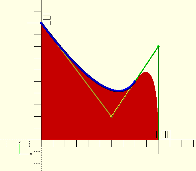
T/t
T/t (Nx,Ny)+
-
Nx,Ny, next point coordinates, see convention.
The SVG T/t command yields a quadratic Bézier curve, but it takes no controlpoint.
As above, that should alarm you a little, if not; please have a look at the GHOUL’s
Bézier curve library first.
The controlpoint is a reflection of the previous curve’s last controlpoint in the current point.
Even though there’s a failsafe built into the specifications, a smooth Bézier curve command only makes sense after another Bézier curve command.
If the previous command isn’t a curve, there’s no controlpoint to reflect after all…
It accepts multiple parameter sets, all of which take only the next point, and all of which will have smooth transitions thanks to their reflected controlpoints.
The code snippet below contains the call that would result in the accompanying image.
SVG("M 0 0 H 100 Q 100 80 80 50 T 0 100z");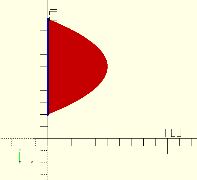
V/v
V/v (Coord/Dist)+
-
Coord/Dist,
V/vonly takes one parameter, which has two different meanings, Coordinate or Distance, depending on whether the command is absoluteVor relativev. In an absolute call it draws a line to the point with X=Px and Y=Coordinate. In a relative call it draws a line to the point with X=Px and Y=Coordinate+Py.
It is possible to give V/v multiple Y-coordinates or distances, but since it’s a 1D command, that doesn’t seem to make a lot of sense. Either way, the library will deal with them correctly, according to the SVG specifications.
The code snippet below contains both the absolute and the relative call that would result in the accompanying image.
SVG("M 0 20 V 100 Q 100 60 0 20z") // absolute
SVG("M 0 20 v 80 Q 100 60 0 20z")  // relative
Behind the scenes
|
|
The functions discussed in this section are what makes this SVG library tick 'behind the scenes', they are NOT user routines, you’ll never call them directly. |
SVG path-strings are a chain of commands, each executed after the other, each starting off where the previous command left off.
The GHOUL’s SVG library works just like that.
After a command has generated it’s points, it calls the next command — via SVG_NextCommand() — and so on.
The commands all share the same set of parameters, they are passed from command to command as the path is 'drawn' and points are added.
To avoid repetition, only A/a is discussed here, just because it’s at the top of the alphabetical list…
SVG_…() functions
SVG_A(PathCommands,CC,Paths,LastCommand,Calls=1,PointsOnly=false)
-
PathCommands, array, all SVG subpaths and commands that
SVG()is processing. This is a 3D array, in this format: [svg shape[subpaths[command parameters]]].SVG()processes the paths and commands like a chain of function calls; each command calls the next until the last returns it’s points and the whole chain cascades back to return the final result. -
CC, tuple, a 3-tuple containing the indices of the current path, command and parameter, it points to 'where we are on the path at this moment'.
-
Paths, array, the vertices of all subpaths and commands processed so far. The last vertex of this path is also used as the 'current point' for successive calls.
-
LastCommand, tuple, the endpoint and last curve controlpoint of the previous command. It’s a convenient way to pass the current point to the next command, and the last controlpoint of previous curve commands, needed by 'smooth' Bézier curve calls to calculate their own (first) mirrored controlpoint.
-
Calls, scalar, counter of commands processed so far. This is only to inform the user at the end of the process, it has no function in the routines.
-
PointsOnly, Boolean, if true, the function will not hand control to the next command, but return an array containing only the points it has generated.
After a command has generated it’s points or line segment, it advances the parameter index by the length of it’s own parameter sets. The parameter index now points at the first parameter of the next set (if there is another set in this command) or it points past the end of the command (the index is greater than len(Command). SVGNextCommand() uses this information to decide whether to call the next command, or the same command with the next parameter set.
SVGNextCommand()
SVGNextCommand(PathCommands,CC,Paths,Points,LastCommand,Calls)
-
Points, array, points generated by the previous command
-
For the other parameter descriptions see
SVG_Aabove.
SVGNextCommand() has three main functions:
-
Add the Points generated by the previous command to Paths.
-
Call the next command in the path:
-
If the next command is a 'moveto'
M/mcommand, start a new subpath first. -
Call the next command with the updated CC and Paths parameters and incremented Calls parameter.
-
-
Return Paths and Calls when the shape is complete.
SVGNextCommand() is the nerve-center, it sends the path-string to the successive commands, processes their output, keeps track of the current point and last controlpoint, counts the command executions for bragging rights, and finally returns the finished polygon points and paths to SVG().

SVGParsePath()
SVGParsePath(PathString)
-
Pathstring, string, any valid SVG path-string.
SVGParsePath() is used by SVG() to parse the SVG path-string into an array so we can address the individual commands and parameters.
It takes the initial path-string, uses SVGMovePositions() to find the 'moveto' commands and cuts the path-string into subpaths at their locations. Then it separates the commands in each subpath using SVGPathCommandPositions() and parses them and their parameters using SVGParameterPositions().
The image has nothing to do with SVGParsePath() per sé, but I got so exited and made too many, I had to put it somewhere…
|
|
I’m not discussing those last few functions here; there’s no sense, and the curious can check the .scad files, they’re commented profusely, remember, this is The GHOUL. |
Future plans and notes
I intend to write a function for chamfers, as well as one for circular fillets, probably soon, but not today; today I’m tired. Coffee. Coffee is what I do for the rest of today…

That, there, in the image, is Wobble() working away. It’s a bonus function, combined with
Tumble() in Tumble.scad. Have a look. It does exactly what it says, it makes an object 'wobble', I’ll write the documentation soon, not today, today, you know, coffee…
This image, and all others on this page, is included in The GHOUL in the Demofiles directory in SVG_Images.scad You’ll see I cheated a little; by tilting the image 'North' a bit, the wobble effect gets more 'depth'.
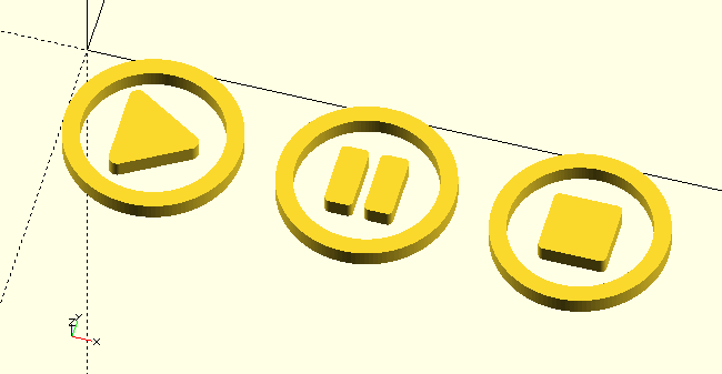
TheGHOUL/DemoFiles/SVG_Images.scad is full of SVG path-strings you can have fun with. Go on, you know you want to… The images are all on single, commented lines, like in the code snippet below so just un-comment the line of the image you want to see.
//Eye
//translate([-300,300])linear_extrude(30,twist=5)SVG("M288 144a110.94 110.94 0 0 0-31.24 5 55.4 55.4 0 0 1 7.24 27 56 56 0 0 1-56 56 55.4 55.4 0 0 1-27-7.24A111.71 111.71 0 1 0 288...